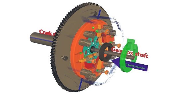
Here we are trying to demonstrate the concept of the working of a single plate clutch. Ask any three students to come forward to participate in the role play. Let one student act as a flywheel, the other one as a clutch disc, and the third one as a pressure plate. The students who play as clutch components will explain the working of the single plate clutch during engaged and disengaged positions.
Make the remaining students into 3 groups. Let one group prepare a chart showing the figure of a single plate clutch and explain its working; the second group also explain the working but by using an actual clutch and the third group may explain the function of each component of the clutch. The teacher can evaluate each student according to their performance.
MULTI-PLATE CLUTCH
The multi-plate clutch is an extension of the single-plate type where the number of frictional and metal plates is increased. The increase in the number of friction surfaces obviously increases the capacity of the clutch to transmit torque, but the size remains fixed. Alternatively, the overall diameter of the clutches is reduced for the same power transmission as a single plate clutch.
This type of clutch is therefore used in some heavy transport vehicles the racing cars where high torque needs to be transmitted. Besides, it also finds application in the case of scooters and motorcycles, where space availability is limited.
A simplified diagram of the multi-plate clutch is given. The construction is similar to that of the single-plate type except that all the friction plates on this are in two sets, ie., one set of plates slides in the grooves on the flywheel and the other one slides on splines on the pressure plate hub. Alternate plates belong to each set.
CENTRIFUGAL CLUTCH
In this type of clutch, the springs are eliminated altogether and only centrifugal force is used to apply the required pressure for keeping the clutch in the engagement position. The advantage of the centrifugal clutch is that no separate clutch pedal is required. The clutch is operated automatically depending upon the engine speed.
This means that car can be stopped in gear without stalling the engine. Similarly while starting, the driver can first select the gear, put the car into the gear, and simply press the accelerator pedal. This makes driving very comfortable and easy. The following figure shows a schematic diagram of a centrifugal clutch.
FRICTION DISC (CLUTCH DISC/PLATE)
The clutch plate consists of a steel plate with a splined central hub. Annular friction facings are attached to the steel plate by rivets. Special resins are also being used to bind the friction facings. A provision of axial cushioning interposed between the clutch plate and friction facing. The curved cushioning spring segments are attached rigidly to the center plate and the friction facings are riveted to these springs. On engagement the load applied first has to compress the spring segments to flat conditions resulting in smoother engagement.
Apart from the cushioning, the clutch plates are also provided with torsional springs to absorb undesirable torsional vibrations. The clutch plate is made into two parts. i.e. a central hub sub-assembly and outer ring assembly, the two being torsionally flexible with each other. The coil spring is placed between the central hub and outer ring under slight compression in the slots provided.
Last word
Common clutch facing materials used are asbestos, Raybestos, Ferodo, and nonasbestos. clutch facing. Due to environmental pollution asbestos, Raybestos and Ferodo are not used nowadays. Non-asbestos clutch facings are used which are made of man-made glass fiber, mixed with a special rubber compound to improve frictional performance, firmly locked with elastomer-based novellas binder, and molded with pressure and heat.
 Tech Readers
