 Tech Readers

Introduction
This unit explains how power flows from the gearbox to the road wheels. The unit describes the necessity, function, construction and working of universal joint and slips joint. It also deals with the construction and working of differential, types of crown wheel and bevel pinion, rear axle casing, rear axle drives, and rear axle shaft supporting methods. The students will be able to dismantle, assemble and diagnose the troubles in the drive line.
Unit in detail
A motor vehicle’s driveline or drivetrain consists of the parts of the power train excluding the engine and transmission. It is the group of parts connecting the transmission with the driving wheels. It consists of a drive shaft (also called propeller shaft), universal joints, slips joint, final drive, differential and half shafts.
Propeller shaft
This is the shaft that transmits the drive from the transmission to the bevel pinion or Worm of drive-in front-engine, rear-drive vehicles and from the transfer box to the front and rear axles in the all-wheel-drive vehicles.
Shaft – As this has to withstand mainly torsional loads, it is usually made of tubular cross-section it also has to be well balanced to avoid whirling at high speeds. Shafts are made of steel, aluminum or composite materials.
One or two universal joints – Depends upon the type of rear axle drive used. The universal joint account for the up and down movements of the rear axle when the vehicle is running. Modern vehicles use, however, high-speed constant velocity joints, and rubber couplings.
Slip joint – Depending upon the type of drive, one slip joint may be there in the shaft. This serves to adjust the length of the propeller shaft when demanded by the rear axle movements. Fig. 6.1 shows a propeller shaft, with two universal joints at the ends and a slip or sliding joint.
A universal joint is a particular type of connection between two shafts, whose axes are inclined to each other. The simplest type of universal joint is the Hooke’s joint which is most widely used as it is simple and compact in construction and reasonably efficient at small angles of up and down propeller shaft movement, say up to 180. The axes of shafts A and B are intersecting. Each of these shafts contains a yoke. Cross C has four arms.
The two opposite arms of the cross are supported in bushes in the yoke of shaft A, while the other two arms of the cross are supported in the yoke of shaft B. Thus shaft A can have an angular rotation about axis XX and shaft B, about the axis YY. It is thus seen that it will be possible with the Hooke’s joint for the shafts A and B to have positive drive while allowing angular movement between them. An improved form of the Hooke’s joint uses a needle roller bearing to support the cross in the yoke and this results in an increase of joint efficiency.
Rzeppa Joint (Constant Velocity joint)
The first real constant velocity joint, still in use, is the Rzeppa joint. In this six spherical – balls are held in a precise geometric position midway between the two shafts, bisecting the angle between them.
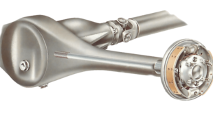
FINAL DRIVE
The functions of the final drive are to provide a permanent speed reduction and also to turn the drive round through 90°. The reduction provided is in cars and in heavier vehicles.
Last word
Then turning one sun gear will cause the other to rotate in the opposite direction. That means if left sun gear rotates ‘n’ times in a particular time, the right sun gear will also rotate n times in the same period but, of course, in the opposite direction. This rotation is super-imposed on the normal wheel speed when the vehicle is taking a turn. Thus the outer wheel rotates at higher speed than the inner wheel while taking a turn.